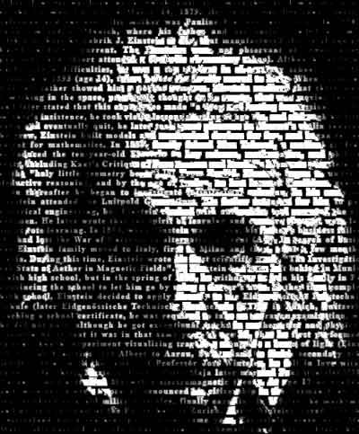
Hi, now it's time to try something different: Photoshop tutorial. In this tutorial I will show you how to create cool photo effect. I will create a face from a lot of text. This effect will looks good on poster, book cover and so on. It has a very strong sense of dramatic feeling.
1. You need a black and white photo. I use Albert Einstein's photo. You can use any photo actually. But, it is recommended that your photo has a strong constrast between light dan dark areas.
If you don't have black and white photo, you can turn color photo into black and white. From top menu choose Image>Adjustment>Desaturate. You can also adjust the contrast between dark and light area using Image>Adjustment>Levels.
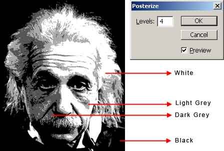
2.From top menu, choose Image>Adjustment>Posterize. Use Levels=4. Posterize will make the photo has 4 colors only, ranging from white to black.
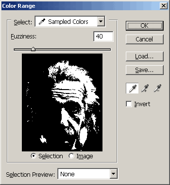
3. Next, from top menu choose Select>Color Range. Click on image to select white area. Click OK.
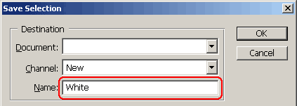
4. You need to save this selection. From top menu Select>Save Selection. Type "White" in Name input box..Click OK. When finished Ctrl+D to deselect.
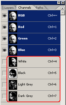
5. Repeat the above process (selecting and saving the selection) to all colors. Finally you'll get 4 selection saved in channels. Open Channels tab to see the saved selections.
In Part 1 tutorial, you have prepared a photo with 4 channels. The next step is to add a text layer and modify it. Be patient, soon you'll get a nice text face effect.
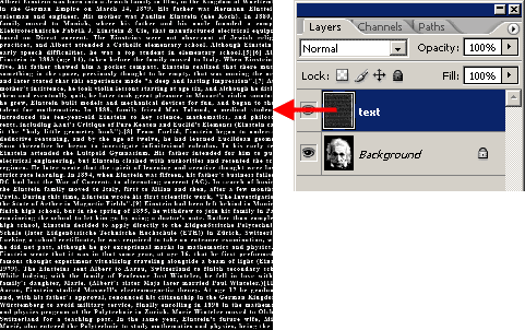
1. Create a text layer like image below and position it above photo layer. This layer is a white text with black background. This layer should be a bitmap.
If you want to create this image yourself, first create new layer and fill with black color. Copy paste any text. now, you have 2 new layers (black color and text). The text should be small enough and continues as a single paragraph. I copy paste from an article about Albert Einstein from wikipedia. Then selelct and merge both layers (Layers>Merge Layers).
You can also download the bitmap text image here. Just open, convert into RGB (Image>Mode>RGB) and drag this image above current poterized photo.
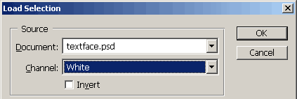
2.Make sure layer "text" is selected. From top menu choose Select>Load Selection. In dialog box, choose White Channel. Click OK.
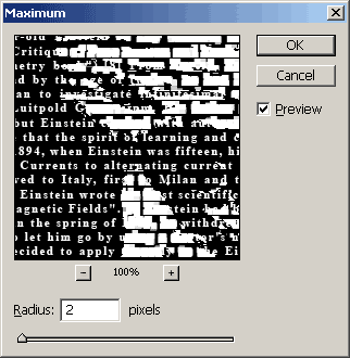
3. Next, from top menu, choose Filter>Other>Maximum. Use Radius=2. Maximize will make selected text brighter and bigger. When finished, deselect the selection (Ctr+D)
4. Repeat above process.
Load Light Grey channel into selection. Apply Feather to make selection more smooth (Select>Feather). Use Feather Radius=5. Apply Filter>Other>Maximum with Radius=1.
Load Black channel as selection. Apply Feather to make selection more smooth (Select>Feather). Use Feather Radius=5. Apply Filter>Other>Minimum with Radius=1.
Leave Dark Grey channel as it is. Or load Dark Grey channel as selection and add Filter>Blur>Gaussian Blur to smooth text edges.
In this tutorial, you will learn to create metallic Transformers Logo using Photoshop. I decided writing this tutorial after I watched Transforrmers 2: Revenge Of The Fallen. You will know that the process of making metallic Transformers logo is not too hard. I believe you will learn a lot from this tutorial.
2. Open Photoshop. Choose File>Open. Open Decepticon EPS file. Use 350x400pixel, 72 dpi, RGB mode. From top menu, choose Image>Adjustment>Invert to change its color to white.
Enlarge canvas (Image>Canvas Size). Use 120 percents x 120 percents.
In Layers Palette, create new layer. Rename this layer 'background'. (To rename, just double click at layer name). Position this layer at the bottom. Fill this layer with black color.
3. Open metal texture image and drag into document. Press Ctrl+T, then rotate and resize metal texture. When finished, press Enter.
4. Next, we need to change texture color into greenish color. Create new layer. Fill with greenish color (R=54, G=75, B=70). Change its blending mode to Color.
Next, select both texture and color layer(hold Ctrl while selecting both layers), and right click at these selected layers. Choose Merge Layers. Rename this combined layer to 'base texture'.
5. Make sure 'base texture' layer is selected. Ctrl+click at Layer 1 icon to load selection. Then click Add Layer Mask to create a masking.
In Part 1 tutorial, you have created base texture for our Metallic Transformers Logo. Next step is to create several more layers and preparing to create another detail.
1. Create new layer on top of other layers. Ctrl+Click at Layer 1 icon to load selection. From top menu Select>Modify>Contract. Use amount=4pixel.
Then fill selection with black ciolor.
2.Turn off other layers's visibility (by turning off eye icon in Layers palette). So you can see this new layer clearly. After Contract, some sharp edges are rounded. Use Polygonal Lasso Tool to select some rounded areas and delete to make them sharp again. Below is several areas that need to be adjusted.
3. Next, select 'base texture' layer. Right click at this layer and choose Duplicate Layer. Rename the duplicate layer to 'top texture' and position this layer above.
In this duplicate layer, right click at layer mask icon, and choose Delete Layer Mask.
Make sure 'top texture' layer is selected. Ctrl+click at Layer 2 icon to load selection. and click Add Layer Mask button to create new mask.
Now you have 2 texture layer. Small one at top and bigger one at bottom.
4. Ctrl+click at Layer 2 again to load selection. Create new layer, name this layer 'line'. From top menu Edit>Stroke. Use green color (R=54, G=75, B=70) with amount=2 pixel..
Next, you can delete Layer 1 and Layer 2.
The preparation is finished. Next step is adding some 3D depth to the logo.
In Part 1, base texture layer is created. And in Part 2 tutorial you have made some preparation by creating line and another texture layer. Now it's time for the true task to create 3D looks. You are going to add some depth into our metallic transformer logo.
1. Select 'base texture' layer. Use Dodge Tool to add some highlight to edges area. Use Burn tool to add some shadows to edges area. Tips use several brush size. To increase or decrease brush size use [ or ].
Look at image below for example. If you do okay, the logo looks like a beveled 3D logo.
2.Select 'line' layer. Change its blending mode to Overlay with Opacity=50%. .
3. Next, select 'top texture' layer. Use large bruzh size to dodge and burn some aeras.
4. Final task is creating some scratch. Create new layer. Use Brush tool to draw some scratch. Use green color (R=54, G=75, B=70). Change its blending mode to Multiply.
To add more effect, you can also apply Filter>Artistic>Plastic Wrap.
5. Image below show finished Metallic Transformers Logo.
In this tutorial, I will enhance Engraved Logo Animation tutorial with some laser beam dan fire sparks. I will use Particle Flow to create fire sparks, and then apply Video Post to create glowing laser effects. If you don't familiar with Particle Flow, an advanced particle system in 3ds max, I suggest that you read Getting Started With Particle Flow tutorial first.
This is what you are going to create:
1. First, you need the finished file from Engraved Logo Animation tutorial. You can download here (ZIP). Load file "engravedlogo_anim_finish.max".
In Front viewport create a cylinder. This is your laser. Use Radius=1.5, Height=400 and Height Segments=1. Position this cylinder at the beginning of animation (lower right of logo).
2. We are going to move cylinder to match the logo animation. Make sure cylinder is selected. Go to Motion tab. In Assign Controller rollout, highlight Position row, then click small button above. In opened dialog box, select Path Constraint. This feature will enable you to make cylinder moving along a path.
In Path Parameters rollout, click Add Path button, and press H in keyboard and choose Line01.
Turn on Auto Key. Then enter % Along Path value until cylinder motion is match with logo animation. You will create a lot of keyframes here. For example, create keyframes every 10-20 frames. If there's keyframes in frame 0 or 300, delete them, because you don't need this keyframes.
When finished, turn off Auto Key.
3. I want to make the laser only appear from frame 20 to 280. Select cylinder. Turn on Auto Key. Move slider to frame 0. Right click cylinder and choose Properties. In opened window, decrease Visibility=0.
Then right click cylinder and choose Curve Editor. In Track View-Curve Editor window, find Visibility in left pane. In right pane, you'll see a keyframe and a graph.
Use Add Keys button to click at graph three times. You'll have total 4 keyframes, next change keyframe position and value using bottom input box. Create a graph like image below.
In Part 1 tutorial, you have created laser using simple cylinder and animate this laser along a path. Next, you will create fire sparks using Particle Flow. If you don't know about Particle Flow, there's a beginner tutorial: Getting Started With Particle Flow
1. In Command Panel, choose Create>Geometry. Choose Particle Sysetms from drop down list. Click PF Source button, Click and drag in Front viewport to create a PF Flow icon. Use Logo size=2.5, Icon Type=Circle, Diameter=6, and use Quantity Multiplier in Viewport and Render=100%. Position this PF Flow icon exactly at the tip of cylinder.
Next, activate Select and Link tool. Link PF Flow icon to cylinder (select and drag from icon to cylinder). Now, PF icon is always attached to the cylinder.
2. Next step, modifying particle properties to create fire sparks. Open Particle View window (press 6). Highlight Birth 01 operator, use Emit Start=20, Emit Stop=280, and Amount=500. This means 500 particles will be emitted from frame 20 to 280.
Select Speed 01 operator. Use Speed=100 with variation=50%. Activate Reverse and set Divergence=60. Scrub slider or play the animation to watch the particle emits.
3. Next, select Shape Facing operator from Depot (bottom of Particle View window), hold and drag to replace the Shape 01 operator inside Event 01.
Use Size=10 with Variation=50%, W/H Ratio=20. This W/H ratio will create tiny long rectangle. shape for each particle.
To enable you view the particle in viewport, select Display 01 operator, and change display type=Geometry.
4. All fire sparks should fall to the ground. Let's add some Gravity. Create>Space Warps. Choose Forces from drop down list. Click Gravity button. Click and drag to create Gravity in Top viewport. Use Strength=0.1
5. To make the gravity into effect. Open Particle View window. Add Force operator from Depot into Event 01.In Force 01 parameters, Click Add button and click Gravity icon in viewport
Next, rotation. Select Rotation 01 operator, and use Orientation Matrix=Speed Space Follow.
Scrub slider or play animation, you'll have nice laser and fire sparks effect
by Didik Wijaya
In Part 1 tutorial, you have created laser. Then in Part 2 tutorial you created fire sparks effects using Particle Flow. The final touch: adding light, material and glowing effects to laser and fire sparks effects.
1. When laser hit the surface, fire sparks emits and the surrounding areas should a little bit lit up. So, create an omni light. Position this light closer to the surface (logo). You can use any color you want. Here I use combination of red and yelow color.
Using Select And Link tool, link this light to cylinder.
Next, we need to make light only lit from frame 20 to 280. Select light. Turn on Auto Key. Move slider to frame 0. Decrease Multiplier=0. Then right click light and choose Curve Editor. In Track View-Curve Editor window, find Multiplier in left pane. In right pane, you'll see a keyframe and a graph.
Use Add Keys button to click at graph three times. You'll have total 4 keyframes, next change keyframe position and value using bottom input box. Create a graph like image below.
2. Let's add material to the scene. Open Material Editor. Create two similar material with different color. One for laser (red) and the other for fire sparks (yellow).
Here's the material settings, 2 Sided, Self Illumination is active and change the color in Self-Illumination. And the most important thing, set Material Effects ID=1. Rename the material.
Apply laser material to cylinder at the scene (click and drag laser material to cylinder).
3. To apply fire sparks material to particle, open Particle View window. Add Material Static operator from Depot into Event 01. In Material Static parameters, click button under Assign Material. In openend window, select Browse From: Mtl Editor, choose "spark" material.
4. Next is adding glowing edges, From top menu choose Rendering>Video Post. In Video Post window, click Add Scene Event button. Choose Camera viewport.
The, click Add Filter Event button. Select Lens Effect Glow from drop down list. Click OK.
Finally, click Image Output Event button. Click Files button. Save your video later to any name you want dan format you want.
5. In Video Post window, double click Lens Effect Glow to setup some properties. To enable you viewing the scene, move slider to any frame, click Preview button, VP Queue and then Update button.
In Properties tab, uncheck Object ID and check Material Effects ID=1. From now on, all materials with Eddects ID=1 will have glowing effects.
Click Preferences tab. Use Size=2, and Intensity=50%.
6. Finally, render the scene. In Video Post, click Execute button (running man icon). Choose frame range and ressolution.
You may have tried Engraved Logo Animation Tutorial. Guess what? Techniques applied in that tutorial can be used in many cases. For example, like this tutorial, creating tire tread marks animation. In this tutorial you are not only learn to create tread marks, but also creating engraved tread marks effects when tire crossing sand or snow. Note: This tutorials is requested by Dave Van Dyke.
This is what you are going to create:
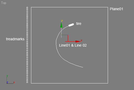
1. First download this file (ZIP). Open file "treadmarks_start.max". This file contains several objects. There are treadmarks objects, tire, two lines and a simple plane. Line01 and Line02 are basicaly the same line but with different height. I have animated the tire using Path Consttraint, based on Line02. Treadmarks object is just a series of spline applied with Extrude modifier. This treadmarks object has black color applied.
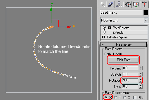
2. First step is deforming the treadmarks to match the path of tire animation. Select treadmarks object. Apply with Path Deform modifier. Click Pick Path button and click Line01 in viewport.
Use Rotation=90 and Axis=X. Then, you need to rotate deformed treadmarks object in many axis to match with the line.
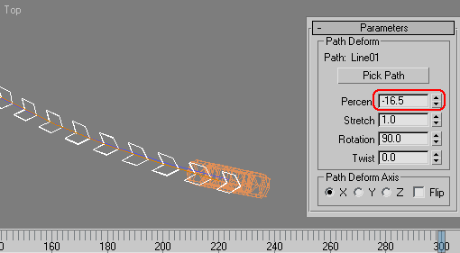
3. Move slider to frame 300 (end of animation). In Parameters roolout, change the Percent value until the tip of treadmarks object is at the middle of tire.
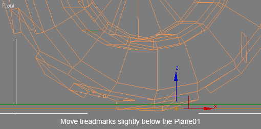
4. In Left viewport, move treadmarks object a little bit below the Plane01 (ground). What we need to do next is to move the treadmarks objects little by little up above the ground.
by Didik Wijaya
In Part 1 tutorial you have created a treadmarks along spline (tire animation path). Next, in this tutorial I will show you how to animate tread marks, making the tread marks slowly appear on the ground.
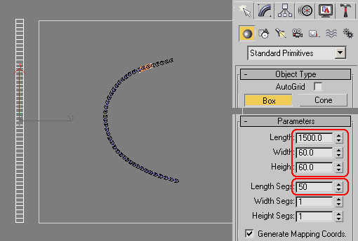
1. In Top viewport, create a box like image below. Use Length=1500, Width=60, Height=60. And Length Segs=50. Basically the box should have bigger size than tread marks.
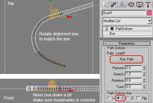
2. Select box, apply with Path Deform modifier. Use Line01 as path, Axis=Y. Rotate deformed box to match the line in top viewport. Finally, move box down a little bit. Make sure treadmarks object is covered by the box..
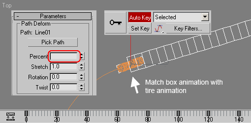
3. Select box. Adjust Percent value to match box animation with tire animation. The tip of the box should be always at the middle of tire (viewed from Top viewport). Move slider to frame 20. Activate Auto Key. Adjust Percent value every 20 frames. When finished, turn off Auto Key.
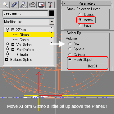
4. Select treadmarks object. Apply with Vol Select Modifier. In Parameters rollout, Activate Vertex. Select by=Mesh Object. Then click button under Mesh Object, and click box in viewport. Play animation, you should see vertices in treadmarks become selected when collided with box.
The next step is moving selected vertices above the plane (ground). Apply treadmarks object with XForm modifier. In Modifier Stack, click plus (+) sign and highlight Gizmo. In Front or Left viewport, move Gizmo (yellow cross) slightly above the Plane01. Now, selected vertices will be moved at the same height as the Gizmo.
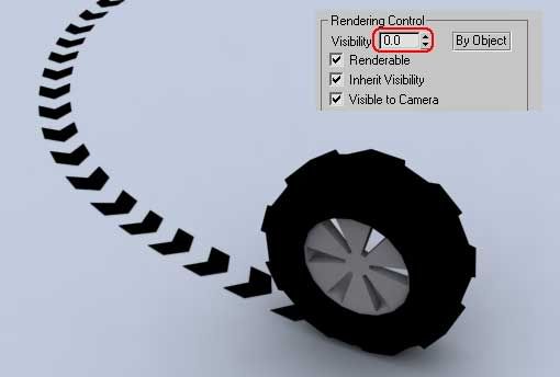
5. Don't forget to make the box invisibible. Right click box, choose Properties, and change Visibility=0.
Image below shows finished render up to this point. In some cases, this tutorial can be considered as finished. Tread marks using simple colored patterm like image below maybe enough for many situations.
But, the coolest part is in the next tutorial section. I will show you how to make engraved tire tread marks animation, when tire is rolling on the sand or snow..
by Didik Wijaya
After creating simple tire tread marks animation in Part 1 and Part 2 tutorial, in this tutorial section I will show you how to create engraved tire tread marks animation. Unlike other tutorials which you use a lot of polygons to create engraved effect, in this tutorial you won't need much polygons here.
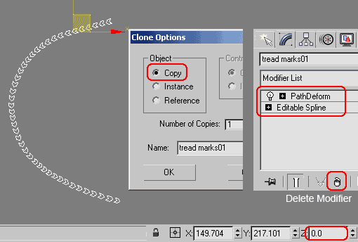
1. Continue with previous lesson file. Select treadmarks object. Move this object exactly at Z=0. (You can activate Select And Move tool, and enter Z=0 at the coordinate input box at the bottom of the screen).
Shift+click to create another duplicate. Use Clone Option=Copy. By default, duplicate object will be named as treadmarks01.
Select treadmarks01 object. Go to Modify tab. Delete several modifier in Modifier Stack, until you only have 2 rows: Editable Spline and Path Deform. Now, treadmarks01 is a deformed spline.
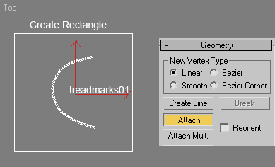
2. Create Rectangle as big as Plane01. Then delete the plane (Plane01). You don't need this object anymore.
Notice that you now have treadmarks01 and rectangle. Select Rectangle, right click and choose Convert to>Convert to Editable Spline. Go to Modify tab, in Geometry object, click Attach button, and click treadmarks01 object. Both objects are combined as one spline.
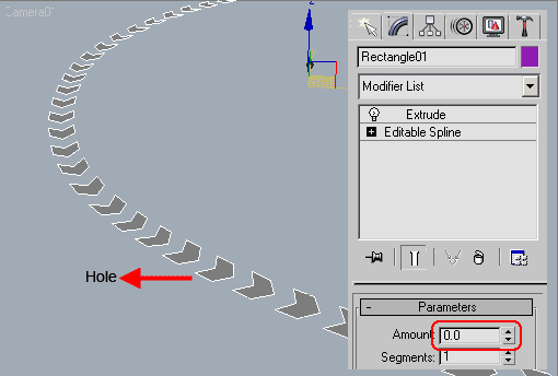
3. Apply combined spline with Extrude Modifier. Use Amount=0. Now, you have a plane with holes. Fortunately, we have treadmarks object. This object is used to fill the holes. Just apply the same material or color to both objects (plane with hole and treadmarks)
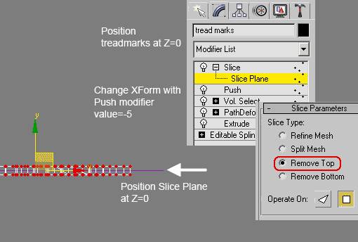
4. Select treadmarks object. In Modifier Stack, delete XForm modifier. Apply Push Modifier. Use Amount=-5. Push modifier will create an engraved looks, but the engraved effect is too high. We need to slice by half. Apply Slice modifier. In Modifier Stack highlight Slice Plane sub object. Position slice plane at Z=0. Then in Slice Parameters rollout, choose Remove Top.
5. This tutorial is finished. Video below shows sample of finished engraved tire tread marks animation..
 Hi, now it's time to try something different: Photoshop tutorial. In this tutorial I will show you how to create cool photo effect. I will create a face from a lot of text. This effect will looks good on poster, book cover and so on. It has a very strong sense of dramatic feeling.
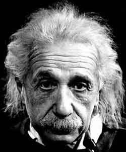
 In this tutorial, you will learn to create metallic Transformers Logo using Photoshop. I decided writing this tutorial after I watched


 In
In 


 You may have tried